Hardware Guide
Pinouts
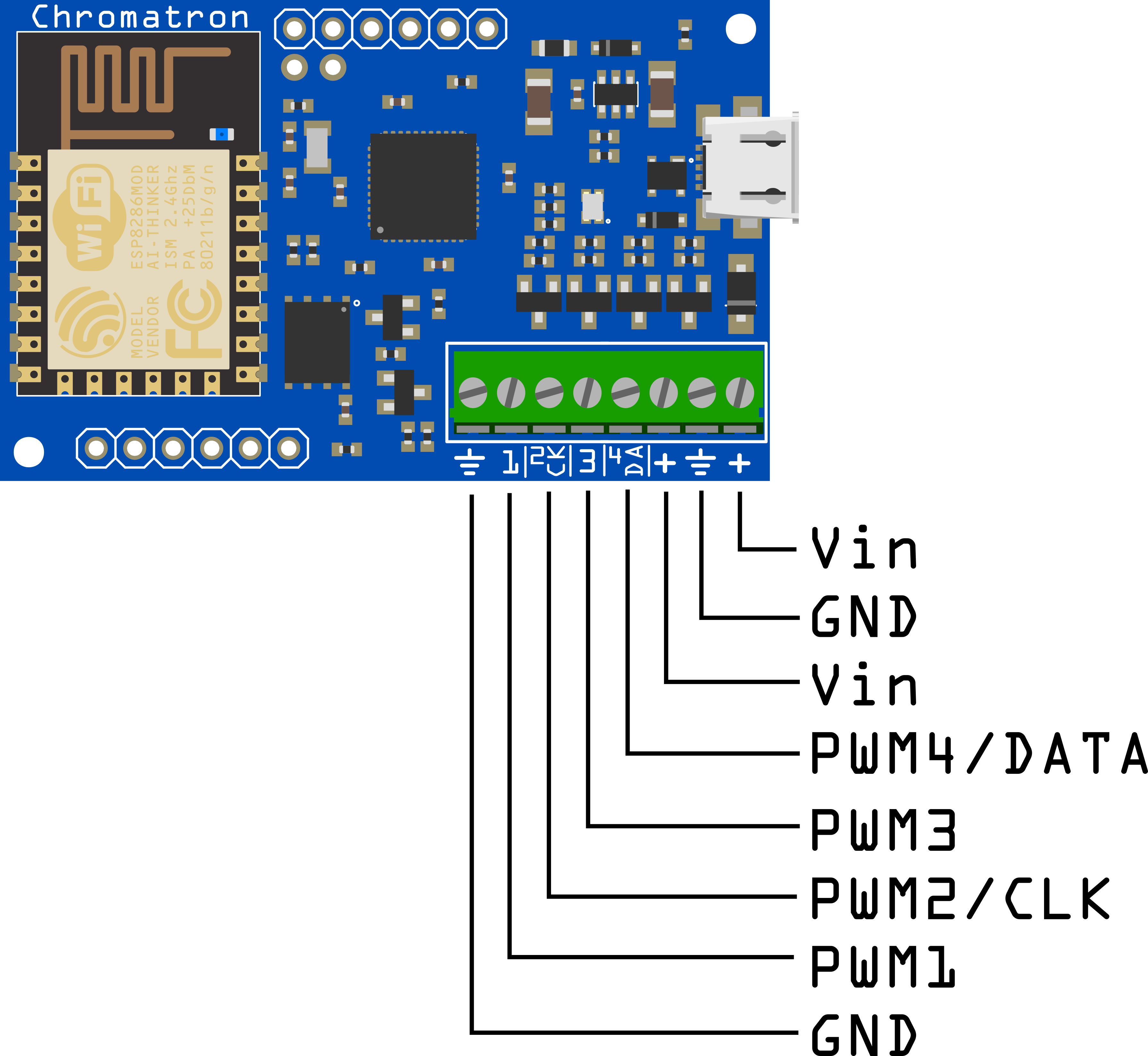
Power
Vin - 4 to 16V power supply connection
Vin must match the supply voltage required for the LEDs. Thus, if you are using 5V LEDs, Vin needs to be 5V. The same goes with 12V LEDs.
Warning
Double check your supply voltage before powering on for the first time! If you’re powering Chromatron on 12V and plug in 5V LEDs, you’re going to damage the LED strip (Chromatron itself will be fine).
Note
Note that in the case of the WS2811 at 12V, the data and clock drivers with automatically limit their output to less than 6V (the WS2811 power is 12V, but signalling is nominally 5V).
GND - Ground connection
There are two sets of power pins. Both Vins and both GNDs are shorted together in the PCB with thick traces. You can supply power to the board with one set, and use the other as power connections for the LED strip.
IO
PWM1 - PWM output for analog pixel mode
PWM2/CLK - PWM output or pixel clock, depending on pixel strip mode.
PWM3 - PWM output for analog pixel mode
PWM4/DATA - Pixel data output. This can also be a spare PWM channel, however, this is not yet supported in the current firmware version.
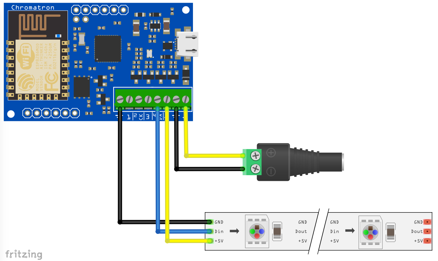
LED Connections
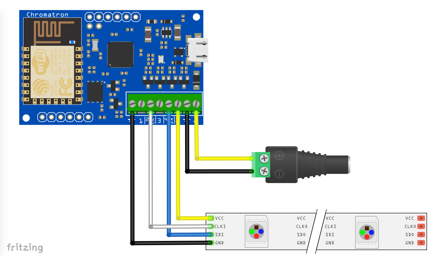
3 Wire (WS2812, WS2812b, WS2811, Pixie)
3 wire LED strips use one set of power connections and data. Clock is not used.
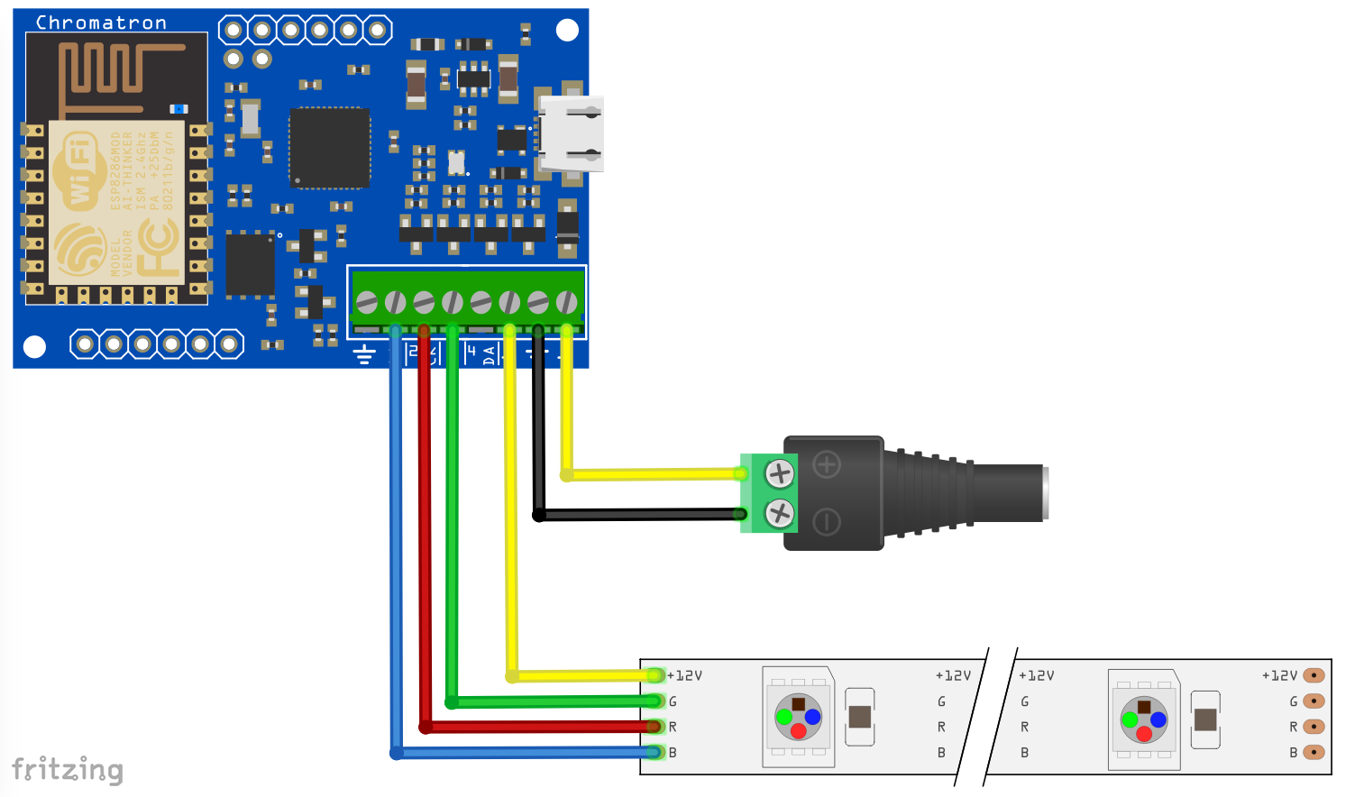
PWM
PWM strips use PWM1, PWM2, and PWM3. Connect on of the Vin connections to the strip’s power input. You do not need to worry about the RGB order, it is configurable in software.
Specifications
Vin - 4V to 16V
PWM channels - Max. 3 amps each
Pixel channels - 320 addressable channels